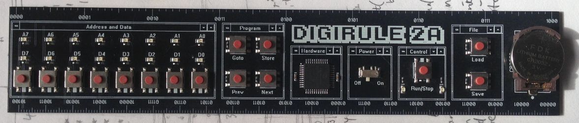
One of the young digital makers at Stafford Raspberry Pi Jam had a Digirule 2, a programmable binary computer built into a PCB ruler. I wanted one instantly; but Brad only has them manufactured in small batches and, as the product is popular, it is usually out of stock. I put my name on the waiting list and in passing the time, researched the Altair 8800 computer system that had inspired his project.

An original MITS Altair (from early 1975) is a rarity but there is a good virtual emulator on the web with interesting support notes and links to an original manual.
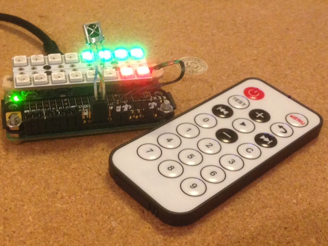
I bought one of Brad's computers as soon as I was notified that they were back in stock. It's a great piece of kit; entertaining and educational. I kept thinking that it should be possible to create a similar 8-bit computer using the BBC micro:bit, a single-board pocket-sized computer. This week I was inspired to achieve that objective. The picture below shows the micro:bit using microPython code to emulate the Altair 8800 with just enough instructions implemented to run the simple program example from the manual, 'to add two numbers located at two memory locations and store the result elsewhere in memory.' The photo shows the emulator at address 0x03 with op code 0x47 MOV(A->B).

A number of issues needed to be addressed in order to adapt to the different form factor. The 5x5 grid does not allow for a row of 8 indicators and two buttons are far less than the inputs available on the Altair or Digirule.
The micro:bit does however, feature an accelerometer and we can use this to add extra calibration to button presses. By reading the tilt roll value we can toggle different LEDs across our grid and the tilt pitch will allow us to select rows. Since it will be sensible to split our 8-bit indicator into two rows of 4-bits, this leaves a spare row and column to provide visual feedback on which LED is about to be toggled. We can therefore, accurately select 16 LEDs using button A and the accelerometer: in fact, we only really need to select 8 LEDs to provide data input. We will use the bottom two rows for data input and the next two rows to show the program address. Button B will be used to navigate the memory addresses.
My first prototype was written using makecode blocks and although this was progressing well, a number of considerations made me decide to move to microPython.
The project progressed much faster than I anticipated and even the implementation of programming features was easier than I expected. I plan to add more instructions in the future but the emulator already demonstrates 8-bit programming with the ability to save and load programs: it also works as a simple binary to decimal or hexadecimal translator.
The button functions are outlined in the image above but to recap:
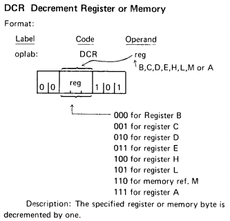
Here is a list of the implemented operating codes using the Accumulator and Register B. I am providing two address bytes although one would be perfectly functional since program memory is currently set at 256 bytes. This is the updated list of implemented operating codes.
Decimal Hex Binary  Mnemonic    Bytes   Action
7   0x07    0000 0111   RLC     1   Accumulator bit shift left
13  0x0D    0000 1101   DECC    1   Register C - 1
15  0x0F    0000 1111   RRC     1   Accumulator bit shift left
50  0x32    0011 0001   STA     3   Store Accumulator in address
58  0x3A    0011 1010   LDA     3   Load Accumulator with contents of address
60  0x3C    0011 1100   INRA    1   Accumulator + 1
61  0x3D    0011 1101   DCRA    1   Accumulator - 1
71  0x47    0100 0111   MOVBA   1   Move Accumulator to Register B
79  0x4F    0100 1111   MOVCA   1   Move Accumulator to Register C
118 0x76    0111 0110   HLT     1   Halt program execution
128 0x80    1000 0000   ADDB    1   Add Register B to Accumulator
160 0xA0    1010 0000   ANAB    1   Bitwise Accumulator & Register B
168 0xA8    1010 1000   XRAB    1   Bitwise Accumulator ^ Register B
175 0xAF    1010 1111   ANAA    1   Bitwise Accumulator ^ Accumulator
176 0xB0    1011 0000   ORAB    1   Bitwise Accumulator | Register B
194 0xC2    1100 0010   JNZ     3   Jump to address if zeroflag false
195 0xC3    1100 0111   JMP     3   Jump to address
On reboot, the emulator will have a clear memory. If you load a program (A, 3 clicks B) it will load the sample program given in the Altair manual. If you have saved your own program then that will be loaded. You can toggle a trace feature for the contents of the Accumulator (A, 4 clicks B) which is useful for debugging.
Add Mnemonic  Binary     Action
0   LDA     0011 1010   Load Accumulator with contents of address
1           0000 1100   Address
2           0000 0000   Address
3   MOVAB   0100 0111   Move accumulator to Register B
4   LDA     0011 1010   Load Accumulator with contents of address
5           0000 1101   Address
6           0000 0000   Address
7   ADDB    1000 0000   Add Register B to Accumulator
8   STA     0011 0010   Store Accumulator in address
9           0000 1111   Address
10          0000 0000   Address
11  HLT     0111 0110   Halt program
12          0000 0001   Data
13          0000 0010   Data
14          0000 0100   Data
15          0000 0000   Data
16  LDA     0011 1010   Load Accumulator with contents of address
17          0000 1110   Address
18          0000 0000   Address
19  MOVCA   0100 1111   Move accumulator to Register C
20  INRA    0011 1100   Accumulator + 1
21  DECC    0000 1101   Register C - 1
22  JNZ     1100 0010   Jump to address if zeroflag false
23          0001 0100   Address
24          0000 0000   Address
25  STA     0011 0010   Store Accumulator in address
26          0000 1111   Address
27          0000 0000   Address
28  HLT     0111 0110   Halt program
The code is now hosted on GitHub. Changes to the implemented opcodes and sample programs have been updated above.
Adding additional op codes and another program sample generated some surprises and lead to a project review. I quickly encountered a memory allocation issue and had to temporarily reduce working memory from 256 to 128 bytes to keep the simulator working. This has since been solved by wrapping the memory and program lists in a bytearray function, which I believe reduces the memory required by a quarter. Becoming aware of the memory limit means that, although there is probably room for some extra code, a full implementation of the instruction set is not realistic.
I am considering an option to read ASCII codes and generate text messages. As an 8-bit computer simulator the project can be considered up and running.
RTFM. I have been using op code 0x0 NOP to stop the program running but on reading the Altair manual more carefully I find that NOP is used to insert programming spaces to allow modification of the code. I have therefor implemented 0x76 HLT as op code to halt program execution and 0x0 NOP now increases the program counter by 1: I will need to add some failsafe for pc > 256 or just allow index out of range error to crash the simulator.
I have also been reading the Intel 8080 manual and added some bitwise operators ANA_B, ORA_B, XRA_B and XRA_A (useful for clearing the Accumulator). I instantly encountered memory allocation problems again. The quickest solution is to reduce the memory array from 256 to 128 but I prefer to keep the memory addressing in line with the index range allowed by the data entry. After experimenting with reducing variable name length, removing comments and white space, changing and trying the Minify option in Mu, I was able to gain back the necessary memory by changing all elif statements to if in my op code loop.
That fix seemed fine until I realised that the program was missing steps because the program counter had been updated and was liable to be caught by the next if memory[pc] instruction. Solved by using a dummy if memory[rpc] and updating rpc = pc each loop.
Download hex file for Altair 8080 emulator. Just drag and drop the saved file into your micro:bit.
It wasn't long before I wanted to try and replicate the Altair simulator on a Raspberry Pi. To try and keep the wiring to a minimum, I chose to use neopixels for the display and an infrared controller as the inpu device. I already had experience of using neopixels with the Pi but an IR connecction proved even more of a challenge than I had encountered with the micro:bit. I eventually solved the problem after upgrading my Raspbian to Buster (it may have just been the new install that did the trick), ignoring the promise of LIRC and relying on a pure Python solution by Dewey Dunnington. I looked at another Python solution that implements an event callback module, but I didn't find the results quite as reliable.
The project was able to utilise a lot of the microPython code from the micro:bit project. The routine to interpret the opcodes is almost identical and could now be extended using the extra memory available on the Pi.

I initially used the IR controller number keys to toggle the corresponding data bit but decided to implement an octal base as demonstrated in the original manual and evident in the facia layout in the image at the top of the page. An octal sensibility is also evident in the structuring of machine code instructions.
| FFA25D Exit |
FFE21D Menu |
|
| FF22DD Load |
FF02FD Store |
FFC23D Save |
| FFE01F Back |
FFA857 Run |
FF906F Forward |
| FF6897 0 |
FF9867 Goto |
FFB04F Clear |
| FF30CF 1 |
FF18E7 2 |
FF7A85 3 |
| FF10EF 4 |
FF38C7 5 |
FF5AA5 6 |
| FF42BD 7 |
FF4AB5 |
FF52AD Trace |
IR controller layout.
And then I tried the simulator on an ESP8266 with an ssd1306 OLED running micropython and some helpful IR code by Peter Hinch.
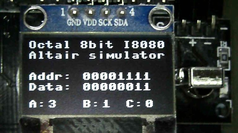
The IR routine collects different codes to the previous libraries but is responsive on the ESP8266. I was encountering a problem saving code files until I realised that I would have to suspend the IR callback routine while writing to file. Adjusting the default data pin for the IR read has enabled me to neatly connect all the hardware using a row of pin jumpers.
I think this is my favourite fabrication so far.
| 45 Exit |
46 | 47 Menu |
| 44 Test |
40 Store |
43 Trace |
| 07 Back |
15 Run |
09 Forward |
| 16 0 |
19 Goto |
0D Clear |
| 0C 1 |
18 2 |
5E 3 |
| 08 4 |
1C 5 |
5A 6 |
| 42 7 |
52 Load |
4A Save |
IR controller layout.
So I wondered how it would work on an iPhone running Pythonista.
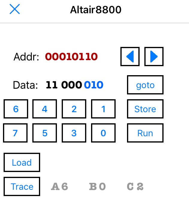
Next, to port it back to the Rasberry Pi with a GUI using TKinter. Having started on the micro:bit with microPython, it has been relatively trivial to port to these different platforms and configurations.